Before you proceed, here’s some things I need to say:
Parts that you have may look different than those in the picture. I’ve tweaked the design of some parts very slightly but didn’t print them
If there’s a conflict between my instructions and CAD, trust the CAD. I’m not that great at writing instructions, and the CAD model is fairly complete. But I didn’t model the T-nuts, so pay attention to those before bolting things up 😛
If something I write doesn’t make sense, trust your intuition. Once again, I’m not the greatest at writing instructions and you guys are all smart people 🙂
There’s around 80-ish 3D printed parts that are required to build FlipSide. Most of these parts have less than a 60mm x 60mm footprint. The only parts that may be of concern is the handle (120mm x 18mm footprint) and the front and rear bed “tie bars” which have a footprint of 220mm x 20mm. However, these should easily fit on a 200 x 200 print bed when oriented diagonally. I’ve also included STLs of all the parts pre-plated for a 200×200 print bed in the correct quantities. Total print time is in the ballpark of ~40 hours. You shouldn’t need any supports, though decent bridging/overhang performance would be beneficial. Your printer should also print within 0.5mm tolerance (fairly reasonable). I printed all the parts out of PLA filament with 2-3 perimeters and 20% infill.
Tap Extrusions
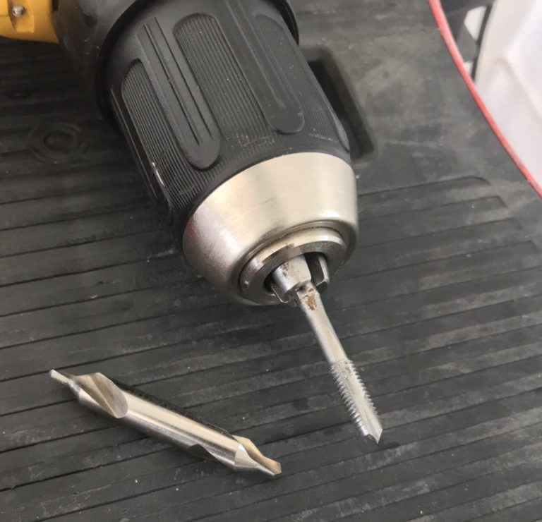
The two 2080 and 2060 extrusions for the bed need to have their ends tapped M5. You can have Misumi take care of this for you, but it will end up costing about $40 more (P/Ns in BOM). I recommend doing this yourself, as a nice, high-speed plug tap like this one is only $5 and has served me really well for a couple years now. In addition to the tap, I’d recommend you have some sort of countersink style bit (I used a center drill, which is by far not the best idea), and some sort of cutting oil (WD-40 works).
Tapping/deburring tools I used (please don’t use a center drill :P)
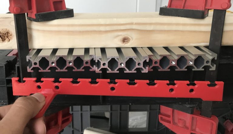
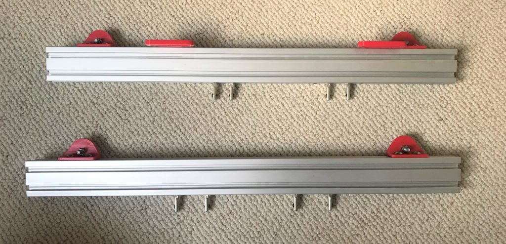
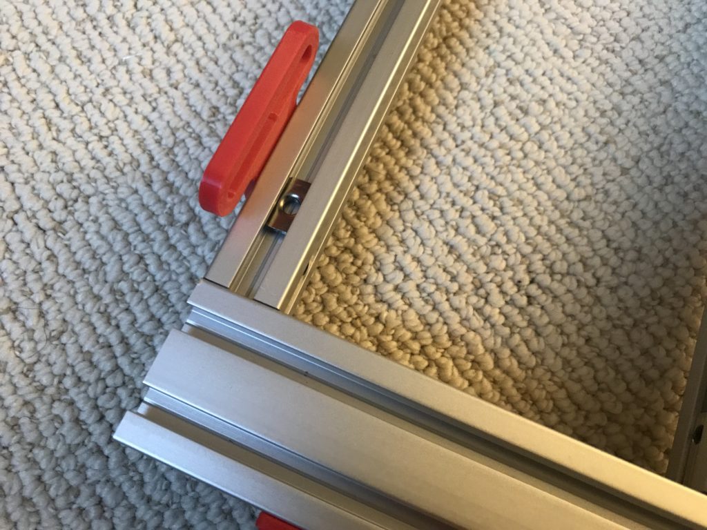
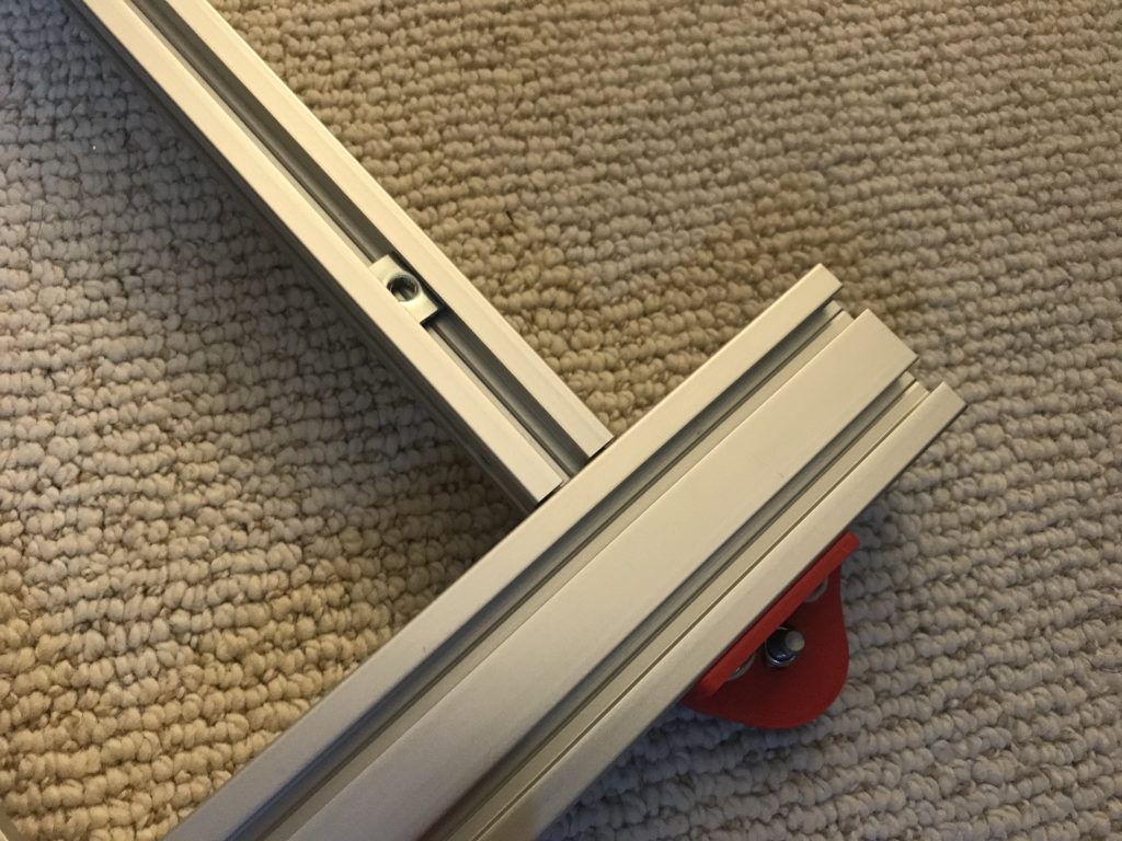
I only tapped the holes I needed to
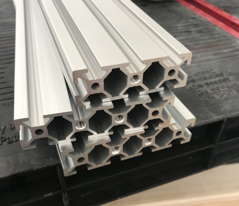
The end product if all goes well! (but the other side is different!)
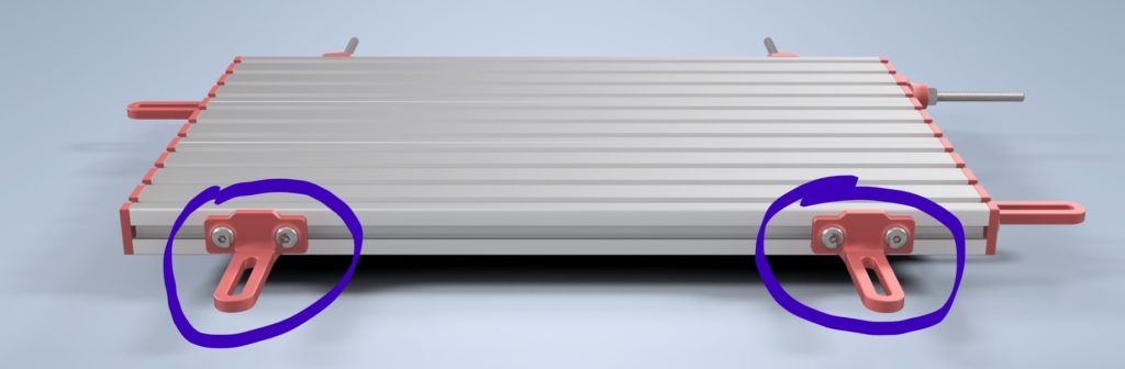
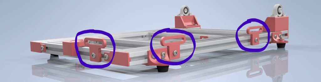
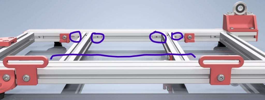
One more note–you don’t need to tap every single hole. These holes are threaded so that the front and rear bed tie bars can bolt to the extrusion faces. This means you only tap the extrusion holes that correspond to holes in the tie bar (hopefully the pic above explains it more clearly). HOWEVER, the front and rear tie bars don’t have the same hole pattern, so make sure to tap the correct holes! I did that so pre-assembly economy t-nuts can be slid in and used in all the slots of the bed.
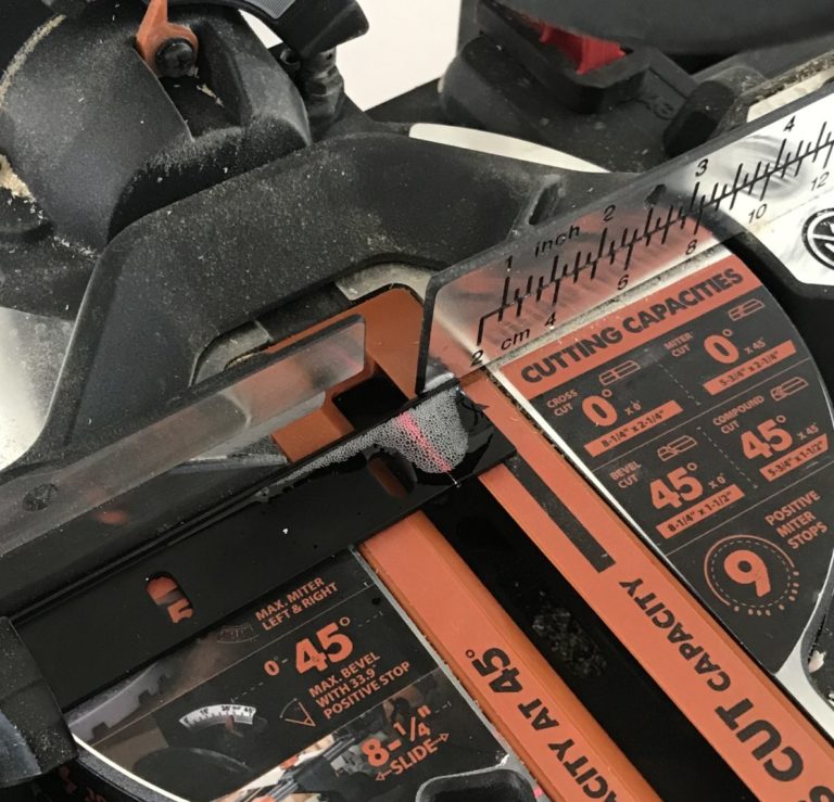
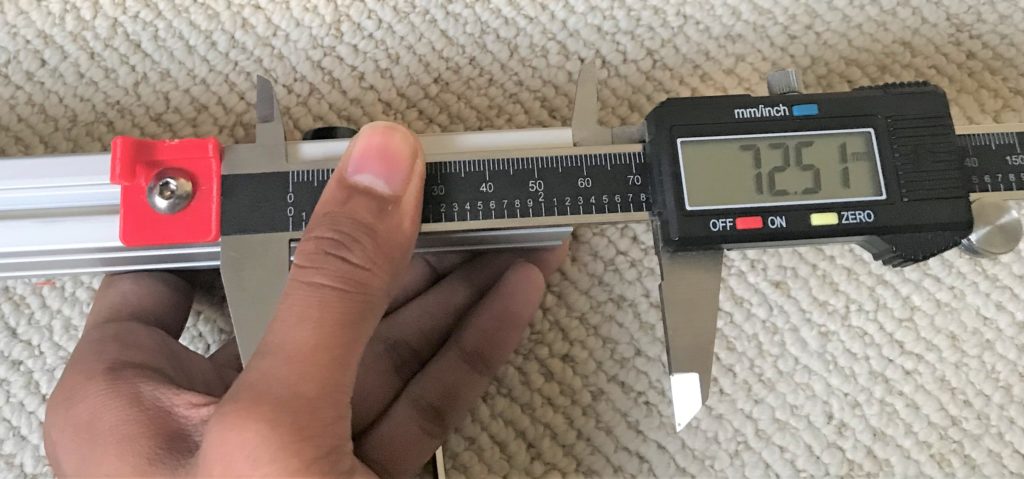
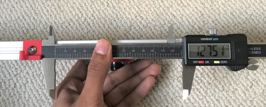
Cut OpenRail to Length
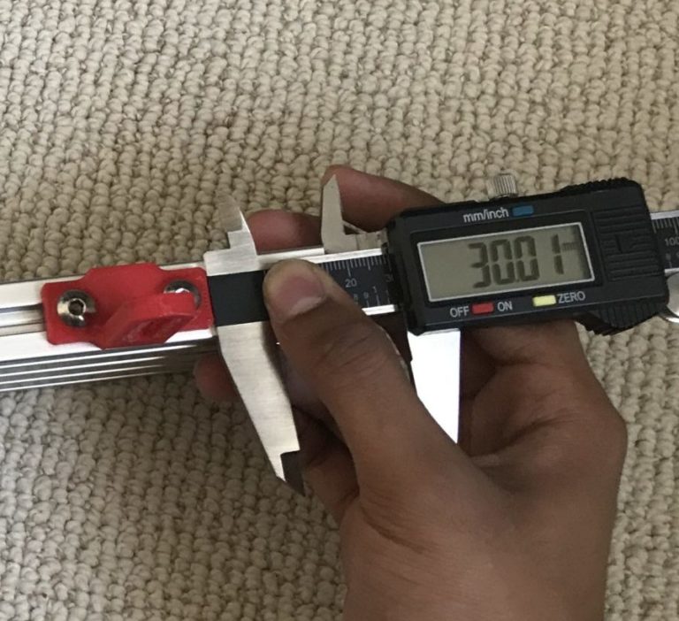
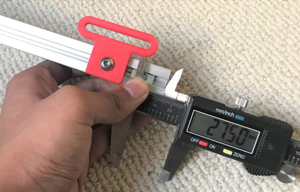
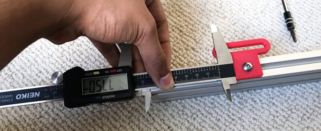
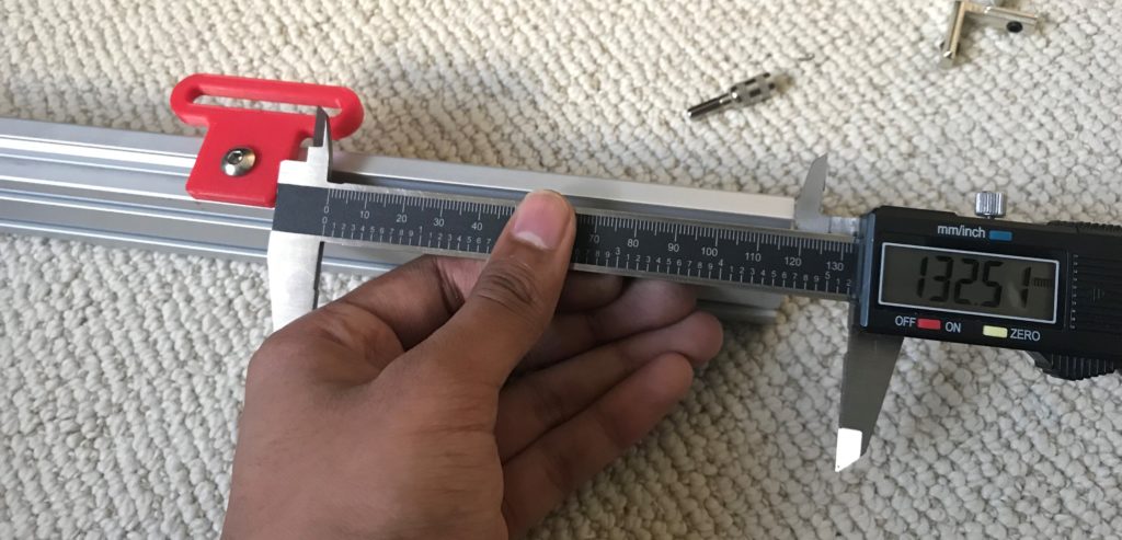
The OpenRail extrusion will arrive in a single 500mm length. We need two 220mm lengths for FlipSide and will need to trim these down to length. You can do this in just two cuts, however, I’d recommend cutting the OpenRail extrusion in four locations, 15 and 235mm from each edge respectively. This will give you five symmetric clamping points on the rail instead of four, slightly offset ones. The rail is thin enough to be easily cut by a hacksaw, but I used a miter saw with an appropriate aluminum-cutting blade to speed up the process. I also used a bit of 400-grit sandpaper to deburr the edges after the cut.
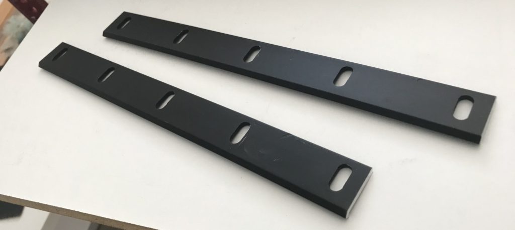
If everything goes right, is should look something like this
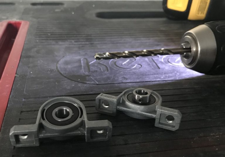
Enlarge KP08 mounting holes
The KP08 bearing blocks are designed to mount with a ~M4 hole, but we need to mount them with an M5 bolt. You can enlarge these holes with a file or drill them out with an appropriate drill bit. Final hole diameter can be anywhere from 5.2mm to ~8mm, so a 1/4″ drill bit should work just fine. I used a 13/64″ drill which is a *bit* (hah) on the smaller side~.
Assembling the Bed
The bed is where you fixture your circuit boards. Before proceeding, please acknowledge the disclaimer at the top of the page.
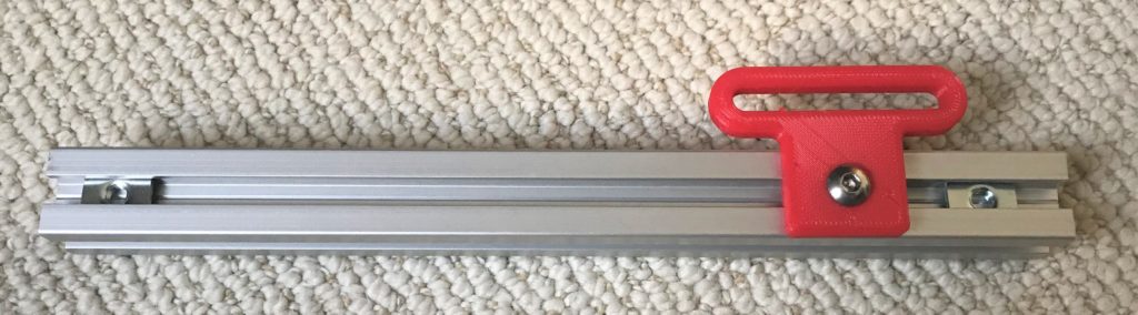
Assemble and Mount the Bed Trim Screw Braces
You’ll need:
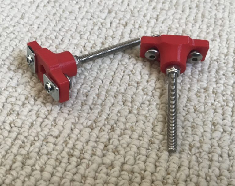
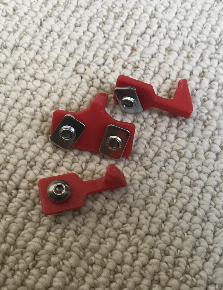
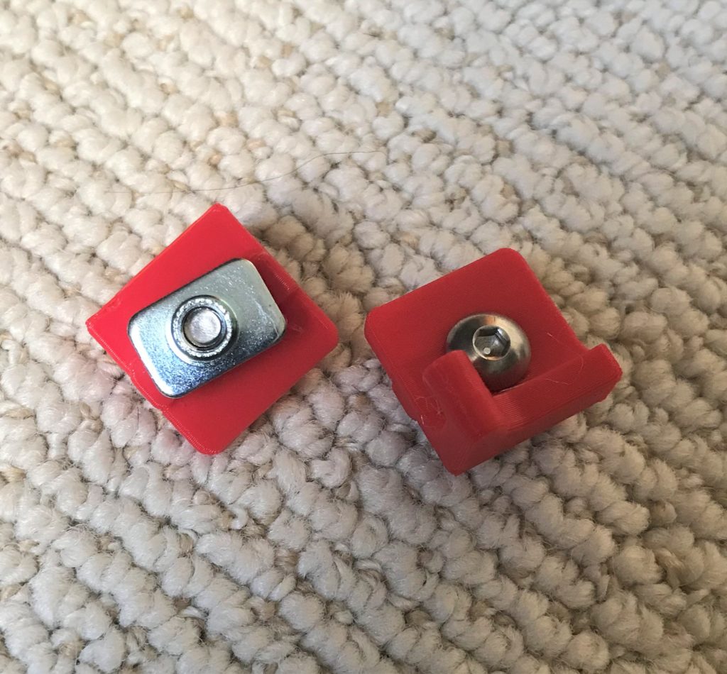
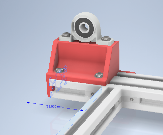
2x Trim Screw Braces (the printed part that looks like the one in the image)
2x M5 x 55mm Hex Bolt
4x M5 x 10mm Screws
4x 2020 T-nut
2x M5 (lock)nut
1x HFS5-2080 Bed Extrusion
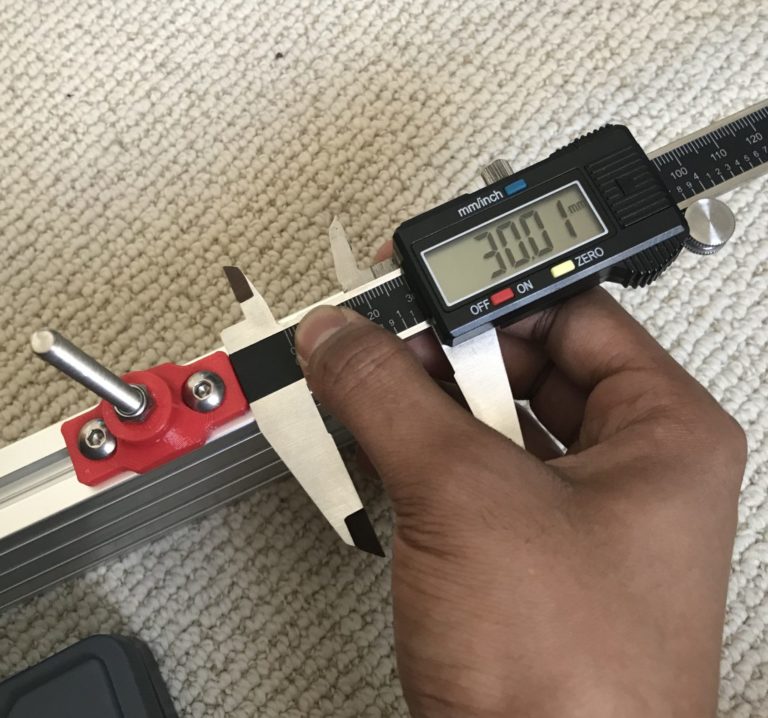
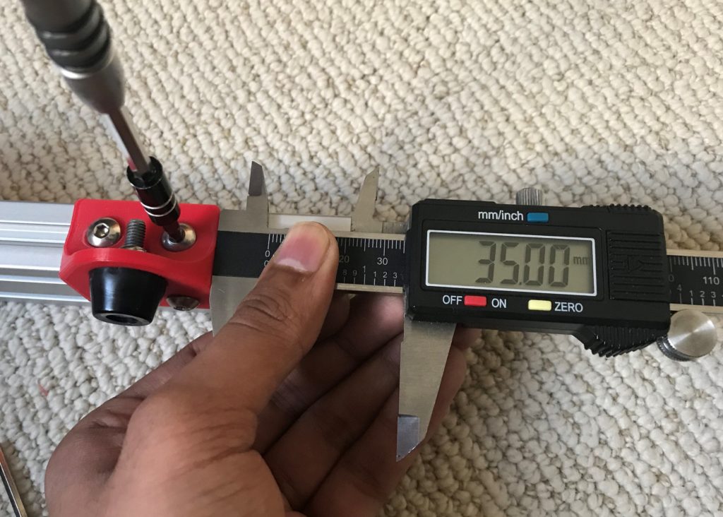
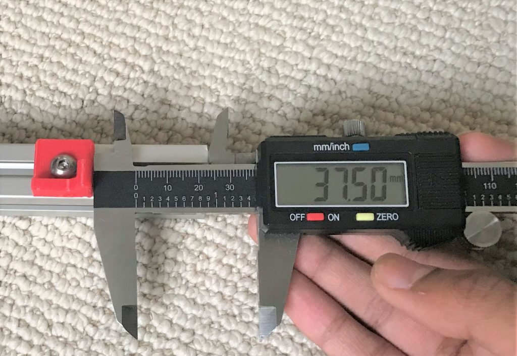
You’ll first need to install the 55mm screws into the printed part. Following that, tighten the M5 nut all the way so it sits flush against the face of the printed part. Yes this is a little annoying if you have a locknut, but using a deep 8mm socket if you have one can be useful. Add the 10mm screws in the remaining holes, followed by the M5 t-nuts. Install these into the 2080 extrusions, with the appropriate 30mm spacing from the end. Make sure the bottom face of these parts sits flush with the bottom of the 2080 extrusion. In fact I’d recommend you tighten these parts down on a flat surface, such as a granite counter top.
Assemble and Mount the Bed Clamp Flanges
You’ll need:
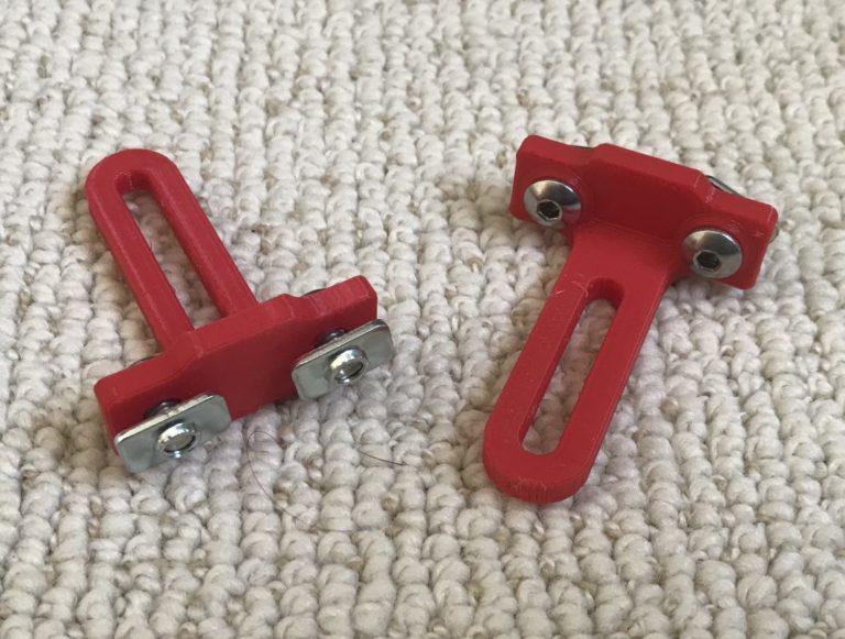
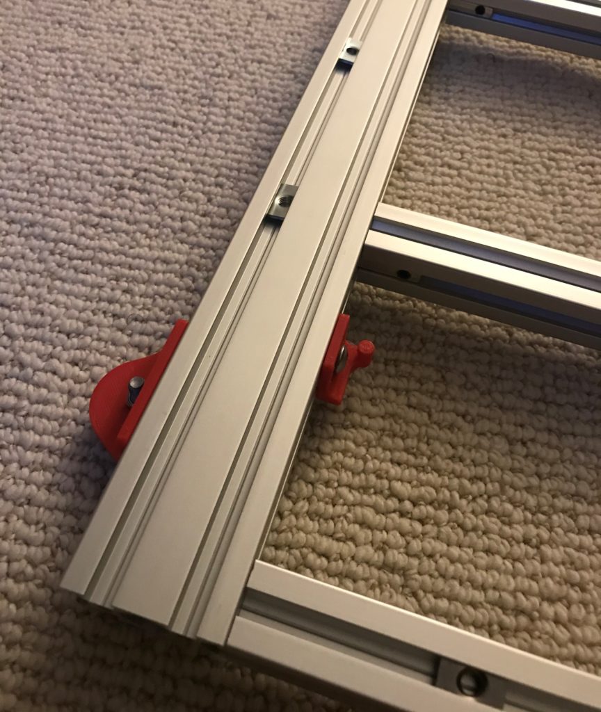
2x Rail Clamping Flanges (the printed part that looks like the one in the image)
4x M5 x 10mm Screws
4x 2020 T-nut
1x HFS5-2080 Bed Extrusion
This one is a little simpler. Just install the 4 10mm screws into the holes as shown, and back them up with an M5 t-nut. After that, install it onto the other 2080 profile, making sure to get the orientation correct (i.e. making sure that the tapped hole patterns are on the correct side). Make sure the bottom face of these parts is flush with the bottom of the 2080 extrusion. My recommendation from the previous step follows here as well.
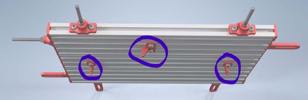
Assemble and Mount the Bed Spring Mounts
You’ll need:
2x X Spring Mounts
1x Wide Y Spring Mount
4x M5 x 8mm Screws
4x 2020 T-nut
1x HFS5-2060 Bed Extrusion
Extrusion assemblies from previous step
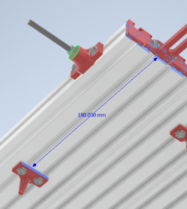
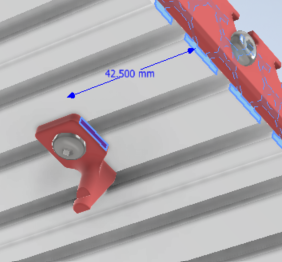
Quick note: The X Spring Mounts will look slightly different than the ones in the first pic–the ones you have tension the spring slightly more. Aseembly is pretty self explanatory I think–install the 8mm screws into the holes into the parts and screw some t-nuts onto the other side. Install in the location/orientation shown in the pictures (180mm for Y mount, 42.5mm for X mount).
Assemble and Mount Bed Tie Bars
You’ll need:
1x Front Tie Bar
1x Rear Tie Bar
1x M5 x 55mm Hex Bolt
1x M5 (Lock)nut
11x M5 x 10mm Screws
Extrusion assemblies from previous steps
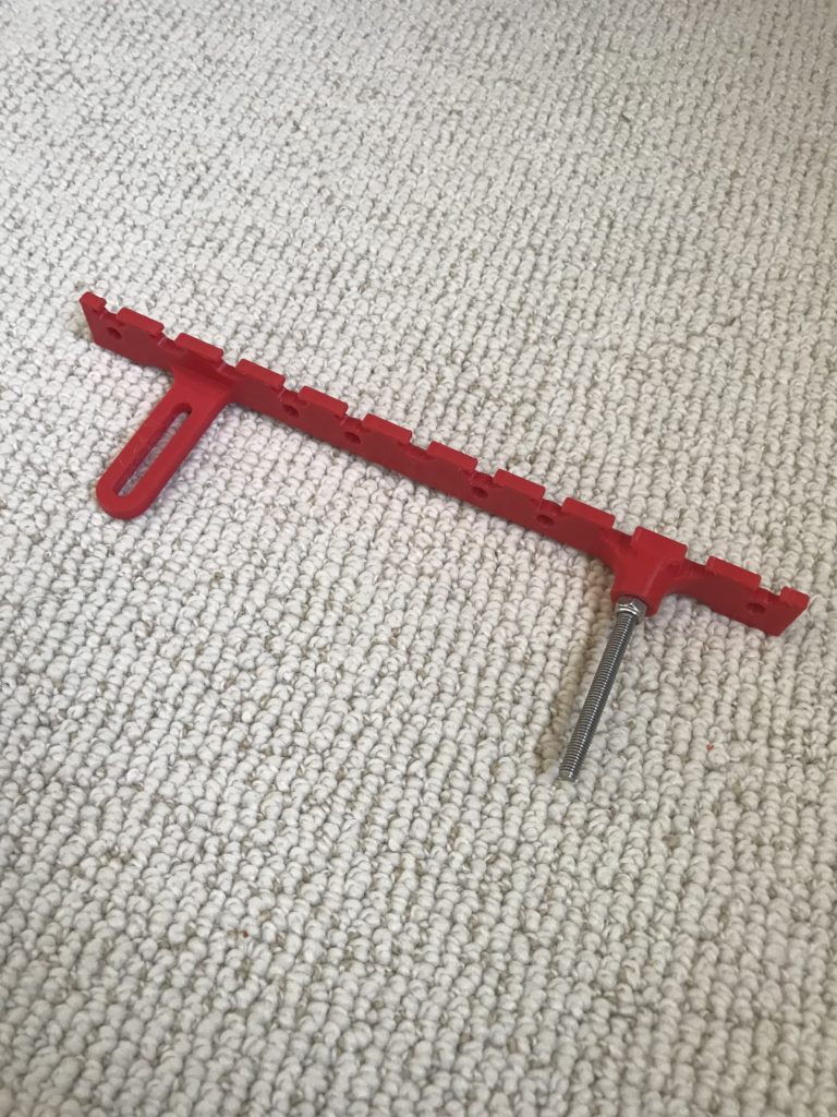
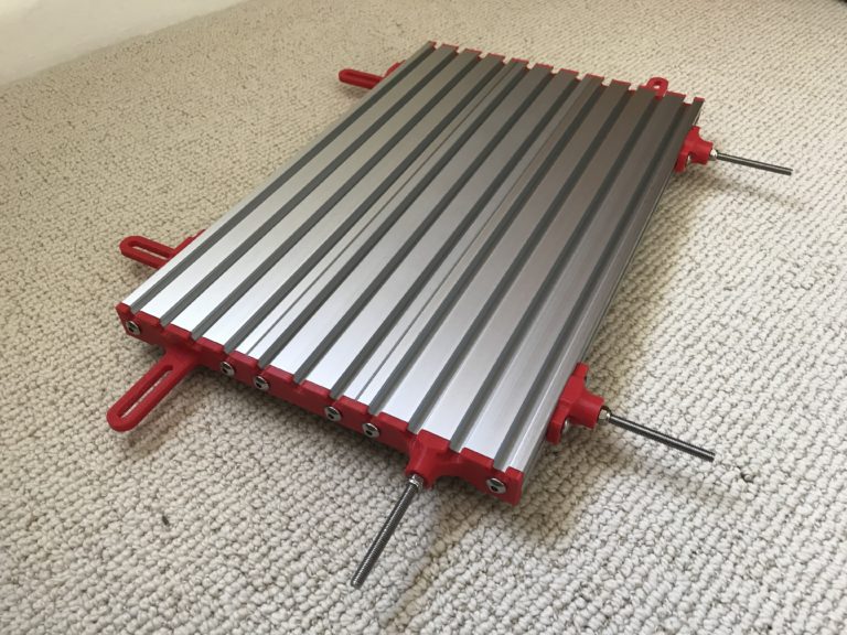
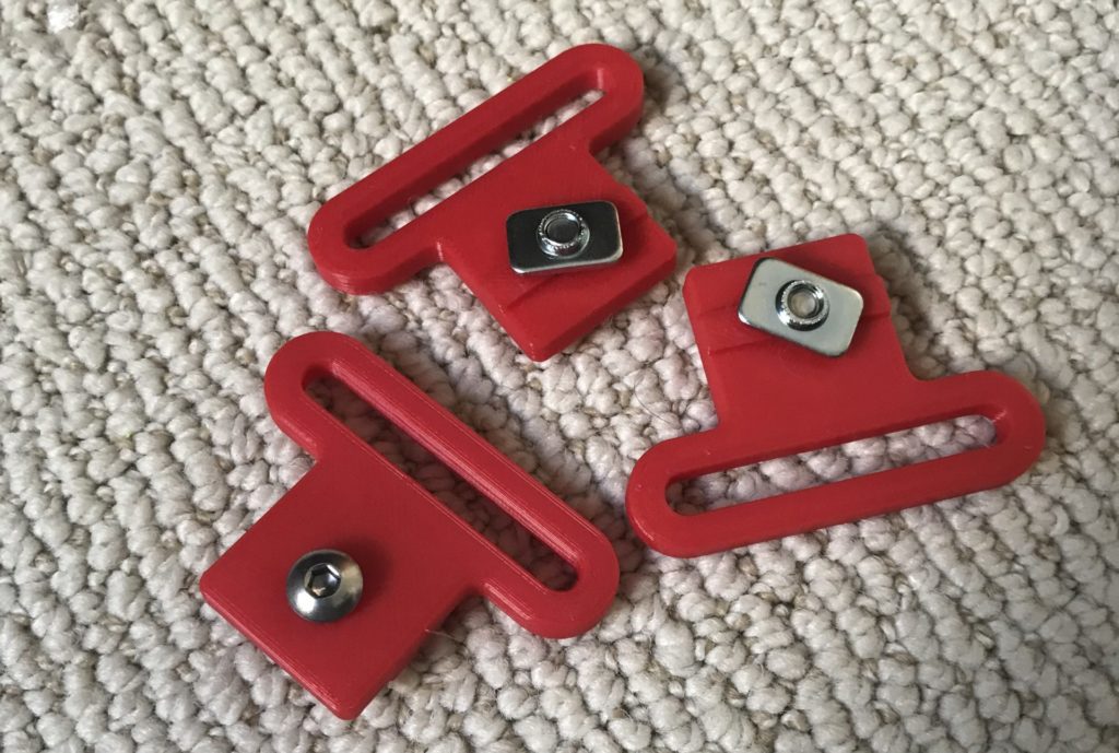
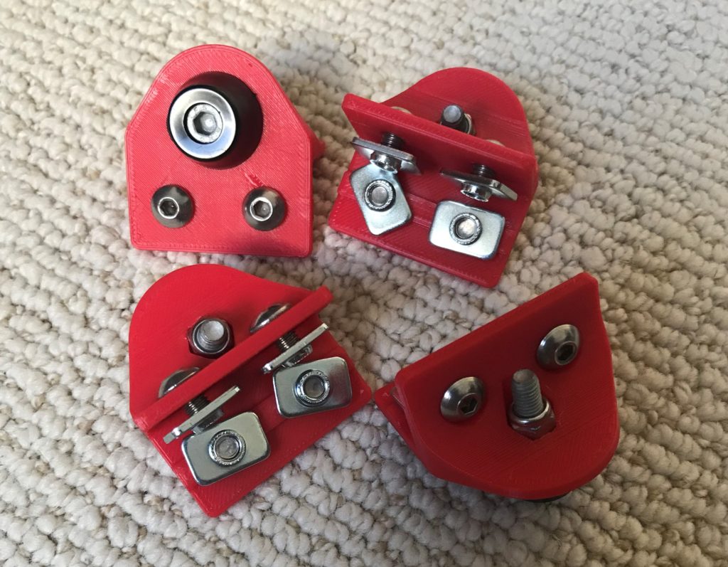
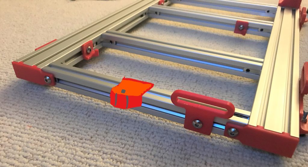
This is the final step of the bed assembly! You’ll first need to install the M5 Hex Bolt into the front tie bar (pictured), just like you did in the first step with the Trim Screw Braces–insert the bolt into the hex counterbore, tighten the M5 nut until it bottoms out against the plastic.
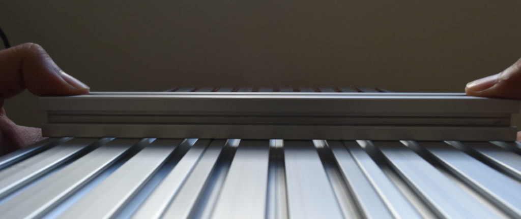
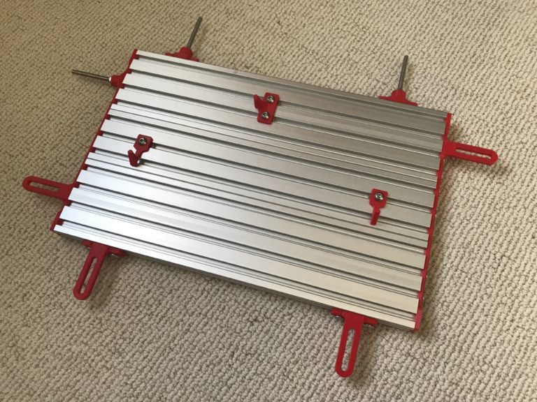
Next, we’ll strap the three bed extrusions together using the two tie bars. It’s imperative that the top of the extrusions are flush with each other. To ensure this, I recommend you grab a handful of the 220mm 2020 extrusions and use a known flat surface, like a granite counter top. Use the 2020 extrusions to space the bed surface from the counter top, ensuring that the short 2020 extrusions aren’t resting against a printed part. Use the 11 10mm bolts to mount the tie bars–make sure they’re oriented correctly (upside down in the picture)!
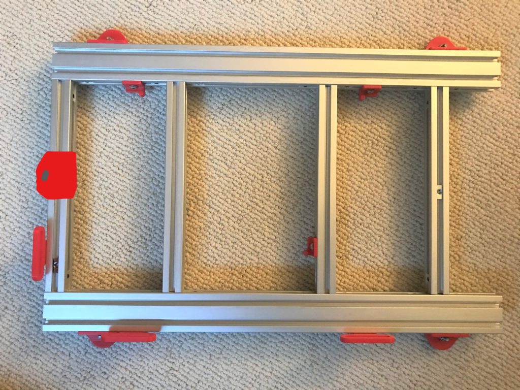
If you did everything correctly, all the bed extrusions will be flush, and you won’t see any gaps when you put a known flat reference against the bed surface.
That’s all for the Bed Assembly!
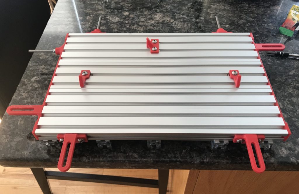
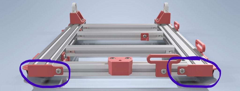
If everything went correctly, it should look something like the following:
Assembling the Base
The bed and the hinge for the clamp frame all sit on top of the base (which seems pretty self-explanatory). Once again, please acknowledge the disclaimer at the top of the page, especially in this section, because this subassembly is the fiddliest to put together and I didn’t to that great of a job taking pictures.
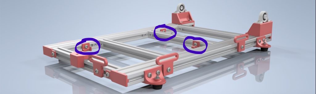
Assemble and Mount Trim Screw Brackets
You’ll Need:
3x Trim Nut Reference (printed part in pic)
3x M5 x 10mm Screw
3x 2020 T-nut
1x HFS5-2040 Base Span
1x HFS5-2020 Cross Span
Prepare the 3 printed parts by inserting the 10mm Screws and loosely screwing the T-nuts in. Slide two of these trim nut references into a 2040 Base Span, spaced 77.5mm and 132.5mm from the edges respectively. The last trim nut reference should be installed 27.5mm from the edge of a Cross Span extrusion.
Assemble and Mount Rubber Feet
You’ll Need:
4x Foot Mount (printed part in pic)
4x Rubber Bumper
16x M5 x 8mm Screws
16x 2020 T-nut
4x M5 x 16mm Screws
4x M5 (Lock)nut
1x HFS5-2020 Base Span
Base Span Extrusion Assembly from Previous Step
Note: The rubber feet and the mounting brackets in the pictures may look slightly different than the ones you have.
First, screw the rubber feet into the foot mounts, using the 16mm Screw and (lock)nuts. Then install all 16 8mm screws and T-nuts. Slide these into both Base Span extrusions 35mm from each end.
Assemble and Mount Height Adjust Bracket
You’ll Need:
Height Adjust Bracket (printed part in pic)
2x M5 x 10mm Screw
3x 2020 T-nut
Cross Span Assembly from Previous Steps
Note: This was kinda a last-minute add-on, so this part may not be properly represented in all following pics
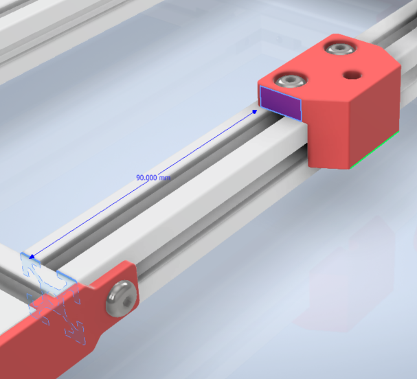
Insert the two 10mm screws into the part, loosely screwing the T-nuts on the back of the screw (just like in previous steps, not pictured). Slide another T-nut into the pocket of the part, with the large flat surface on the “bottom” side when installed into FlipSide. This step can be done later if necessary, just remember to do so. Slide this part into the front Cross Span extrusion, spaced 90mm from the face.
Slide In Hidden Corner Brackets
You’ll Need:
8x Inside Hidden Corner Bracket
Base Span Extrusion Assemblies from Previous Steps
Pretty straightforward; just slide in 4 inside corner brackets on each base span extrusion. Make sure to orient them correctly so that the set screws are accessible!
Assemble and Mount Base Spring Mounts
You’ll Need:
2x Base Spring Mount Right Side (printed part in pic)
1x Base Spring Mount Left Side (not pictured)
3x M5 x 8mm Screws
3x 2020 T-nut
HFS5-2020 Cross Span Extrusion
Base Span Extrusion Assembly from Previous Steps
Note: The new base spring mounts will be slightly shorter than those in the pictures.
Insert the 8mm screws into the printed parts and cap it off with a T-nut, just like previous steps. The right side mount should sit toward the front, offset 72.5mm, the left side mount should sit toward the back, offset 127.5mm. The last right side mount should be slid into a cross span extrusion, offset 37.5mm from the right face.
Insert 2020 T-Nuts for Bed Clamps and Front Endcaps
You’ll Need:
4x 2020 T-Nuts
HFS5-2020 Cross Span Extrusion
Cross Span Assembly from Previous Steps
Not too complicated: slide in a T-nut from either sides of the front face of the front cross extrusion, a T-nut on the top of the front cross extrusion, and a T-nut on the top of the rear cross extrusion.
Bolt Together Base Spans and Cross Spans
You’ll Need:
6x (More) Inside Hidden Corner Brackets
Cross Span Extrusions from Previous Steps
HFS5-2020-Cross Span Extrusion
Base Span Assemblies From Previous Steps
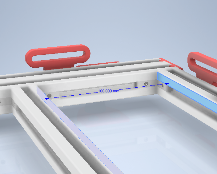
I found this to be the fiddliest part of the assembly. You’ll have to insert and tighten down the 14 inside corner brackets in the base assembly. But be careful. When I was doing this tightening the set screws shifted the locations of the extrusions. My recommendation is to first lightly tighten all the brackets, i.e. tight enough that the set screws are pressed up against the extrusion channels, but loose enough that you can still move the extrusions around with a little bit of force. After lightly tightening everything, make sure all extrusions are still in their proper places (rear extrusion is 55mm from the back face of the base span; inner extrusions are spaced 100mm from the outer ones). Finally, tighten all the brackets down.
Insert T-Nuts for Side Bed Clamps
You Will Need:
2x 2020 T-Nuts
Base Assembly from Previous Steps
This is a quickie; just slide in two t-nuts into the leftmost (when looking from the front) channel of the base spans. These will be used to clamp the bed in place.
Mount Front Endcaps
You Will Need:
2x M5 x 8mm Screws
2x Front Endcaps
Base Assembly from Previous Steps
Note: I used a heat gun to give the endcaps a slight bend; this made sure the they sat flush against the face of the base span even if there was a slight misalignment (due to the previous step)
Other than the note above, this is another straightforward step. Use the 8mm screws to screw the endcaps into the front cross span. There should already be T-nuts in place from a previous step.
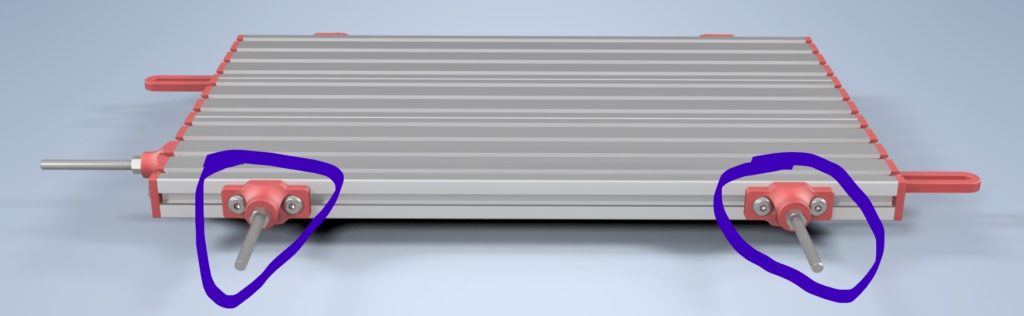
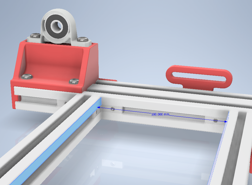
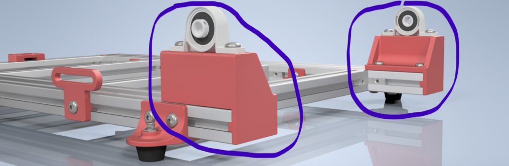
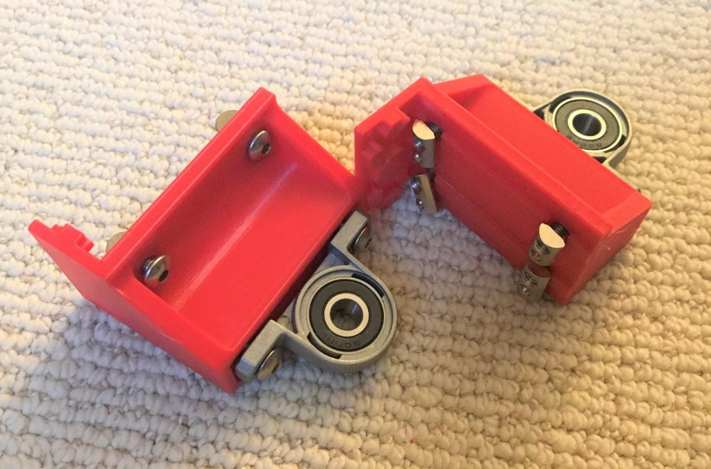
Assemble and Mount Pillow Block Assemblies
You Will Need:
1x Pillow Block Standoff Left
1x Pillow Block Standoff Right
4x M5 x 10mm Screws
4x M5 x 40mm Screws (or Hex Bolts)
2x KP08 Pillow Blocks (Modified)
8x 2020 T-Nuts
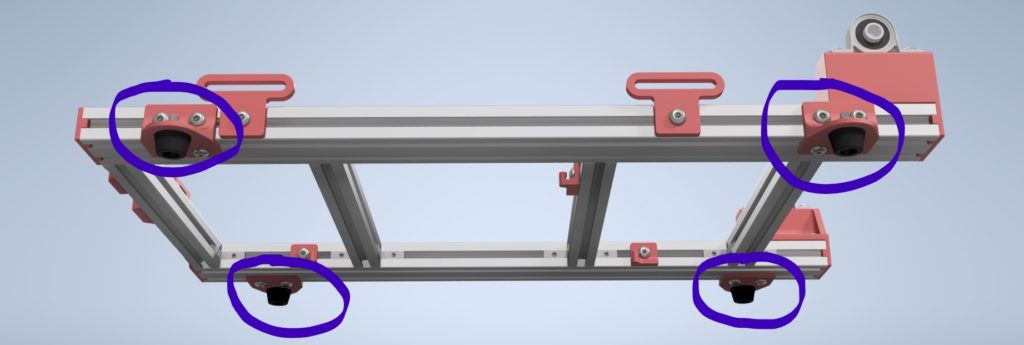
This is the last step for the base assembly! Pass the 10mm and the 40mm screws through the part, with the 40mm screws going through the mounting holes of the KP08s as well. Make sure everything is oriented the same way as the CAD/pictures. Bolt this up and you should be done!
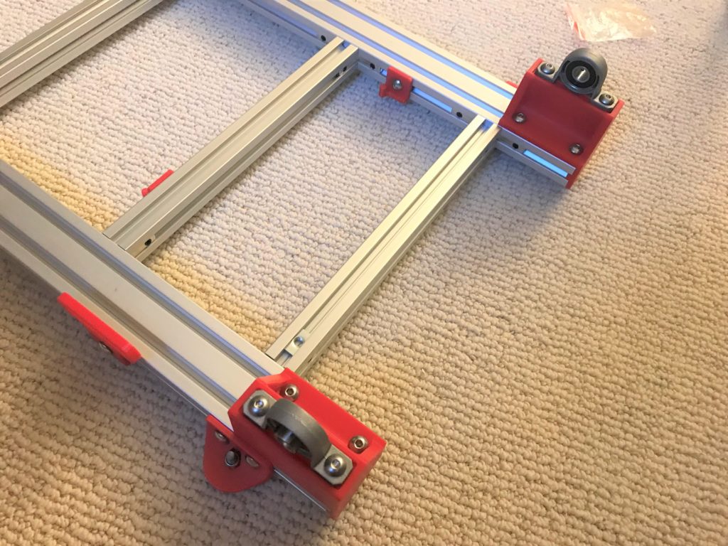
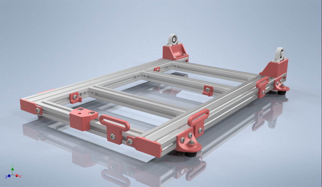
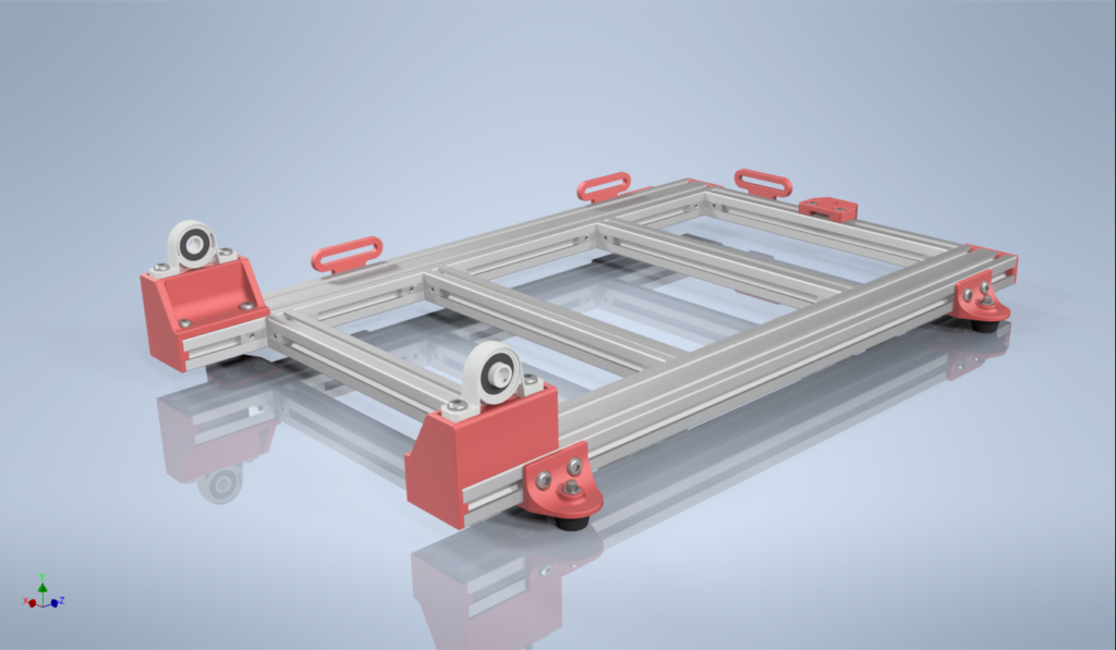
That’s all for the Base Assembly!
If everything went correctly, it should look something like the following:
(Note: This rendering omits 4 2020 T-nuts that should be in the left base span, and front and back cross spans)